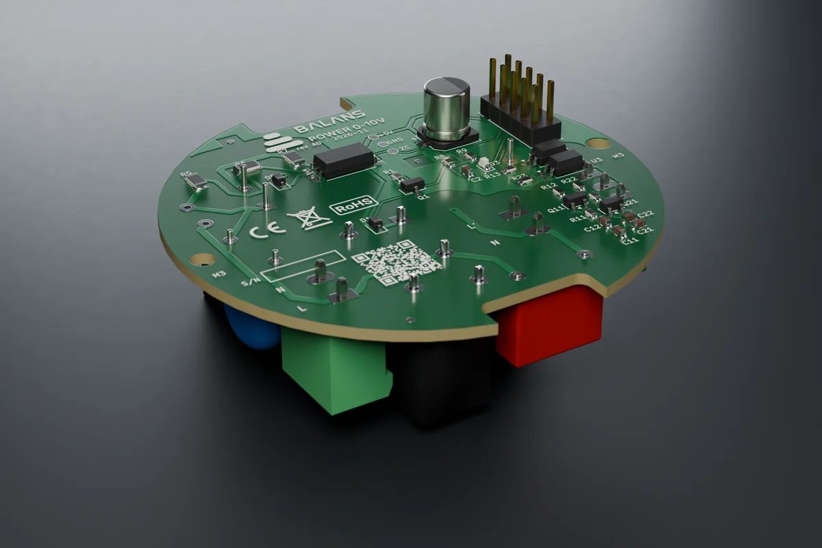
1What the module is for
The module switches the power of an LED driver on and off (zero-crossing relay) and sets the brightness of two drivers or two channels with two 1–10 V lines. The lines are passive according to IEC 60929: the current is supplied by the driver. The 1–10 V side is galvanically isolated from both the mains and the low-voltage part.
Every BALANS switch consists of three layers in a single Kopos box KPR 68-70_KA (depth 70 mm): the front panel FACE behind glass, the control board CORE and the power module POWER at the bottom of the box. The boards are held by a printed carrier screwed into the lugs of the box. The panel and the 84 × 84 mm glass sit in a frame that snaps onto the carrier.
  wall <-------------------------------------------------> room
   POWER module | carrier | CORE | air | FACE panel | glass | frame
        +-- header 2x5 --+          +---- FFC 24p (type B) ---+
2Safety
- The circuit must be protected by an upstream circuit breaker (max. B10, preliminary) and a 30 mA residual current device where required by ČSN 33 2000-4-41 (HD 60364-4-41).
- The fuse in the module protects only the internal power supply. The loads are protected only by the upstream circuit breaker.
- With mains connected, do not plug in the USB-C of the CORE control board and do not remove the front of the switch (frame with panel and glass). The service frame with the USB opening must not be used with 230 V modules.
- The product is only for dry indoor rooms (IP20). Do not use in bathroom zones 0–2 or outdoors.
- Run SELV conductors (low voltage, Ethernet, RS485, sensors) in the wall box separately from the 230 V conductors, with insulation rated for the highest voltage in the box.
- After installation, carry out the inspection and testing per ČSN 33 2000-6 (HD 60364-6) where required.
3Terminals and wiring
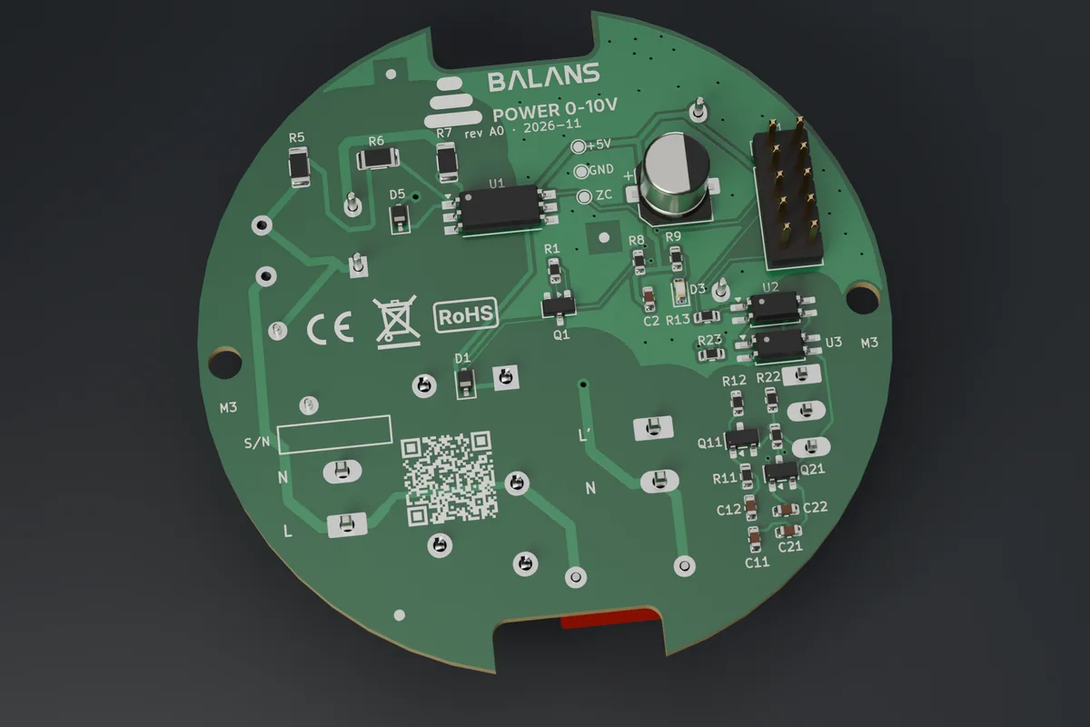
| Terminal | Marking on the board | Connect |
|---|---|---|
| J2 (5.08 mm) | L | phase from the circuit breaker |
| J2 | N | neutral |
| J3 (5.08 mm) | L' | switched phase to the driver |
| J3 | N | neutral to the driver |
| J4 (3.5 mm) | 1+ | 1–10 V control input (+) of driver 1 |
| J4 | 2+ | 1–10 V control input (+) of driver 2 |
| J4 | − | common − of the control inputs |
 breaker --> J2:L --[relay K1]--> J3:L' --> LED driver L
 N ------> J2:N ----------------> J3:N  --> LED driver N
 J4:1+ --> DIM+ of driver 1     J4:2+ --> DIM+ of driver 2
 J4:-  --> DIM- of both drivers
- Drivers that need an active 0–10 V source (some EC fans) cannot be served by this module.
- The 1–10 V lines are passive: the driver supplies 0.1–1 mA.
- The supply relay is shared by both channels. A passive 1–10 V driver cannot switch off, so a channel that is off stays at minimum while the other is on. For two independently switched drivers use two modules.
4Mounting
- Switch off the circuit breaker (disconnect power) and verify that it is de-energised.
- Wire the terminal plugs off the board. The terminals are pluggable: wire the screw plug on the bench according to the terminal table and the markings on the board, then push it onto the pin header on the module.
- Screw the module from behind into the carrier posts (2× screw for plastic 3 × 6). The 2×5 header faces the carrier.
- Run the wires from below along the box wall and into the plugs from the side facing the centre of the board (the terminals face the centre; at the board edge the box wall blocks access).
- Screw the carrier into the box lugs (2× M3 countersunk), arrow pointing up.
- Fit the CORE control board onto the 2×5 header (pins straight, not offset by a row) and screw it down (2× screw 3 × 6).
- Assemble the front on the bench: stick 4 foam pads 1 mm onto the frame posts, place the panel on the 4 pins (M2.5 holes in the corners), put on the 84 × 84 × 2 mm glass and push it under the 4 spring clips. On a frame with glued-in glass, the glass is glued onto the frame shoulder.
- Connect the checked FFC cable type B to the panel and to the CORE board (lock the levers) and snap the whole front onto the carrier.
5Technical data
| Item | Value |
|---|---|
| power supply | 230 V~ 50 Hz, N required |
| switched output | relay for the driver supply, zero-crossing switching, at most one change per second; max. driver power to be added |
| control | 2 × passive 1–10 V (IEC 60929), galvanically isolated |
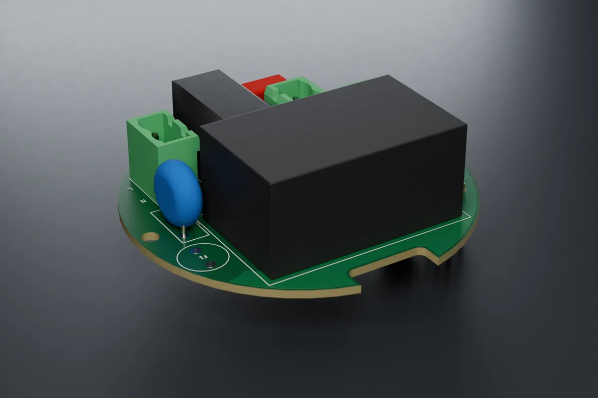
| protection | fuse F1 T2A only for the internal power supply, varistor and X2 capacitor at the input |
| terminals | J2, J3 pluggable 5.08 mm; J4 pluggable 3.5 mm, 3 pins |
| network | Wi-Fi |
| board revision | A0 |
Load ratings are preliminary until heating tests are complete.
Suitable and unsuitable loads
| Suitable | Unsuitable |
|---|---|
| LED drivers and ballasts with a passive 1–10 V input | devices with an active 0–10 V input, DALI drivers (for DALI use POWER DALI) |
6Commissioning
- Switch on the circuit breaker (or connect PoE / power). The front panel lights up.
- Without Ethernet and without a configured Wi-Fi, the switch starts its own setup Wi-Fi “SmartButton-XXXX” (XXXX = end of the MAC address). The password is the 8-digit setup code from the label. The administrator can find it later in the web interface too (card “About the device and support”, button “Show code”, confirmed with the password). On the FACE Display panel the code appears on the display in the settings window (hold the centre for 5 s).
- Connect a phone or laptop and open http://192.168.4.1.
- Set the web password (8–31 characters) and give it to the user together with the label.
- The web interface offers the Setup wizard: name and room, front panel and power module (the wizard shows which module the switch has detected), touch calibration, Wi-Fi and time zone, Home Assistant (MQTT), default button layout and a summary. Nothing is written to the switch before the last step. After a change of panel or module the switch restarts and the wizard continues.
- No output moves until a module is selected. If the selected module does not match the connected one, the outputs stay off and the web interface shows the reason (code E02). A new switch can also select the module by itself: after the first power-on nothing happens, after the second the module is set (POWER Relay and Triac with mains connected, RGBW with the newer board, Base from PoE, PoE IO). The outputs then stay off until someone switches them on for the first time. Heating, blinds and modules in development are not set automatically. If the switch is to stay without a module, confirm “No module” on the Hardware page.
- Test all outputs and touch areas.
- The web interface is then at http://<name>.local or at the IP address from the router. With Ethernet (POWER Base, POWER PoE IO) the switch gets its address from DHCP.
Touch calibration is done through the glass once the front is assembled. It can be started in three ways: in the wizard (step Touch), on the Touch page with the “Calibrate on device” button (the LEDs under the areas guide you: white = do not touch, green = touch and hold, blue = release; at the end green = saved, red = weak area), or right on a new switch without a password: for the first 2 minutes after power-up the LED under the first area slowly “breathes” white, and holding this area alone for 3 s starts the calibration. The areas keep switching as usual meanwhile.
Calibration is also started by a short press of the BOOT button on the control board. On a panel with a slider, the slider finally lights up green: slide slowly along it from one end to the other. After power-on the switch does not respond to touch for about 3 seconds while it measures the idle values of the areas; lights that are to be on after power-on light up immediately.
If Wi-Fi does not connect, the web interface says why in plain words: the network was not found, the password does not match, or the security does not fit. It shows the signal strength with four bars and a word (excellent to very weak) in the header and on the Network page. A hidden network does not appear in the list; type its name by hand.
Web modes: Standard, Advanced and Expert (System → Web appearance). The mode only hides pages and cards an ordinary user does not need. The configured values remain, and warning cards are never hidden. The web interface is in Czech, Slovak, English, Polish and German and is adapted to phones as well. Explanations are short; details open with the “i” button.
Setup mode can be opened again with a gesture: hold two touch areas firmly at the same time for 5 s (FACE Display: the centre of the display for 5 s), or the BOOT button on the control board for 3–10 s. The setup Wi-Fi starts for 5 minutes and the LEDs flash blue. Without Ethernet it also starts when the switch cannot connect to the network for 3 minutes.
Time: the switch takes the time from the internet (NTP). In a network without internet it takes it from the browser after the administrator logs in. Without valid time the scheduler, the night mode and the weekly thermostat programme wait (code E12).
Home Assistant: turn on MQTT and “HA discovery” in the web interface; the entities appear by themselves and are placed in the given room. PLC: Modbus TCP is off by default and is enabled in the web interface (Integrations), preferably read-only and with an allowed IP address. The switch belongs in a separate network (VLAN). Remote access only through Home Assistant or a VPN, never by port forwarding.
Firmware is updated by a technician in the web interface (System → Updates) with a file supplied by the manufacturer. The update is signed. The new firmware is confirmed once the network and the web interface come up after the restart; otherwise the switch rolls back to the previous version by itself within 5 minutes. An update from an address needs a direct link; the switch rejects redirects. Optionally you can enable nightly automatic update from a private https address (off by default): it only runs at the chosen hour, when nothing is lit, no shutter is moving and nobody has touched the switch for 30 minutes. The firmware is not published. This manual describes firmware 2.38.3 (built and signed, not yet verified on the device).
Handover to the customer (System → Maintenance): one action for the installer at the end of the installation. It asks for the administrator password again, offers to set the password of the “control only” user and a new administrator password that only the customer will know (both can be skipped), then it deletes the traces of testing: event log, charts, consumption estimate, log, API tokens, webhooks and the syslog target, and ends all sessions. Optionally it also deletes the stored Wi-Fi. Installation settings, calibration, scenes, scheduler, integrations and passwords remain; the dialog lists which access credentials are left in the switch.
Settings change history (System): the last 8 saved changes with the time and the area they concerned, without values. The “Undo last change” button returns the settings to the state before the last change. Passwords, tokens, keys and the hardware selection are not reverted.
Factory reset from the web interface requires the administrator password to be entered again. With the BOOT button on the board (hold for 10 s) it works without a password; holding it for a shorter time does not reset the switch.
Device health (Diagnostics page): in one word “OK”, “Warning” or “Error”, and below it why and what to do about it. The administrator also finds a list of the last 8 firmware crashes there; if crashes repeat, send it to the manufacturer. The same status is in Home Assistant.
Manuals: the “About the device and support” card has links to the manual for the panel, the module and the control board at benesl-automation.cz/balans/navody/.
Service: System → Maintenance → Service bundle saves one file with the version, status, diagnostics and settings without passwords and keys. It contains network names and IP addresses, so send it only to the manufacturer, not publicly.
7LEDs and module settings
| LED | Meaning |
|---|---|
| green (very dim) | module has 5 V power |
According to the driver in the firmware, the module behaves as two dimmed outputs: the curve, maximum brightness and smooth transition are set as with POWER Triac. The relay closes when at least one output is on, and opens only after dimming has run down to zero.
We will verify the 1 V / 10 V calibration and linearity with a specific driver on the first piece.
8Troubleshooting
| Symptom | Cause | Remedy |
|---|---|---|
| light cannot be dimmed | 1+ and − swapped, active driver input | check the polarity and the driver type |
| minimum is too bright | driver cannot go below 10 % | a different driver; switch-off is handled by the relay |
| a channel that is off glows faintly | the other channel is on, the relay is shared | a property of the module, see wiring |
Special states of the switch
| State | Meaning | What to do |
|---|---|---|
| “Outputs are off” (E02) | the selected module does not match the connected one, the module has no supply, or it is detected but not supported by this firmware | correct the selection on the Hardware page; for a module in development wait for firmware with support |
| “module: none” in the web interface | no module selected | Hardware → select the module, or the wizard |
| LEDs flashing blue | setup mode (5 min) | connect to the SmartButton-XXXX Wi-Fi |
| the LED under the first area “breathes” white | a new switch offers touch calibration (2 min after power-up) | hold this area for 3 s, or leave it |
| three red LED flashes | a fault of severity “error” has occurred | open the web interface, the banner at the top shows the code |
| one area flashes red (E25) | the switch has turned this area off because it would switch by itself (water on the glass, missing calibration) | wipe the glass and wait half a minute; then calibrate the touch |
| only web interface and updates (E01) | safe mode after 3 crashes within 60 s of start | upload another firmware version, send the service bundle to the manufacturer |
| no network (E11) | Wi-Fi or router outage | touch keeps controlling the outputs; without Ethernet the setup Wi-Fi starts after 3 min |
9Error codes
From firmware 2.22.0 the switch reports faults and states as codes E01–E26. It evaluates the state every 2 s, for the first time 8 s after start. An error is reported when it lasts 2–4 s and disappears by itself as soon as it no longer applies. Severity: error = something does not work or is switched off for safety reasons, warning = works with limitations, information = for your information only. The codes only report; the protections of the modules work independently of them.
| Where you see the error | How |
|---|---|
| web interface | a banner at the top of every page: code, name and what to do |
| Home Assistant | entity Fault (problem yes / no) and Errors (list of codes, “OK” without errors) |
| MQTT | topic <prefix>/<id>/faults (codes and English text, “OK” without errors) |
| Modbus TCP / RTU | input registers IR 46 (E01–E16) and IR 47 (E17–E32), bit n − 1 = code En, 0 = no error |
| event log and log | a record when each code appears and disappears |
| LEDs on the panel | when an error occurs they flash red three times; warnings and information do not flash |
| Code | Severity | Meaning | Typical cause | What to do |
|---|---|---|---|---|
| E01 | error | Safe mode | the firmware crashed three times in a row within 60 s of start | Outputs and integrations are off; the network, web interface and updates run. Upload another firmware version, send the service bundle. |
| E02 | error | Power module does not match the selection | a different module selected than connected; module without supply; detected but unsupported module | The outputs did not start. Correct the selection on the Hardware page. |
| E07 | warning | The BME688 sensor stopped responding | loose flat cable to the panel, faulty sensor. A sensor that is not fitted is not an error. | Check the flat cable. An enabled thermostat keeps its output off meanwhile (E09). |
| E08 | warning | Temperature source not available (panel without sensor; 5 min after start at the earliest) | the source switch is off or has a different link key, Home Assistant has not sent the temperature for more than 5 min | Check the source switch or the automation in HA, or select another source (Panel & LED). |
| E09 | error | The thermostat has no temperature (60 s after start at the earliest) | a consequence of E07 or E08, or a thermostat without a sensor and without a temperature source | The thermostat output is off until the temperature is restored. Remove the cause. |
| E10 | warning | MQTT not connected (for more than 2 min) | wrong broker address or password, broker not running, network outage | Check the Integrations page and the broker. Local control keeps working. |
| E11 | warning | No network (for more than 2 min) | cable unplugged, wrong Wi-Fi password, router switched off | Check the cable / Wi-Fi. Local control keeps working. |
| E12 | information | Time is not set (5 min after start) | no access to NTP and after a power failure | Log in to the web interface (the time is taken from the browser), or enable NTP. |
| E13 | warning | Low free memory | many functions running at once (HTTPS, voice) | Switch off unused functions or restart. If it keeps coming back, send the service package. |
| E14 | warning | High temperature of the control board (default threshold 85 °C) | poorly ventilated wall box, high load, high LED brightness | Check ventilation and load. The threshold is in Diagnostics. |
| E15 | warning | Errors on the panel bus | flat cable, connector, interference | Check the flat cable to the front panel. |
| E17 | warning | Hardware check warning | e.g. the display touch controller was not found | Follow the text of the warning in the web interface. |
| E18 | information | The last restart was a crash or a supply voltage drop | firmware fault, weak power supply | If it happens once, nothing; the message disappears by itself an hour after start. If it repeats, send the service package. |
| E19 | warning | Touch has drifted out of tune | cover changed, humidity, dirt on the glass | Only a warning; touch keeps working. Wipe the glass and run the touch calibration. |
| E22 | warning | Automatic update failed, the version is being skipped | the new version was not confirmed after installation, or it could not be downloaded or verified 5 times | The previous version is running. Install manually, or wait for a newer version. |
| E25 | error | The touch area is switched off | uncalibrated panel, water on the glass, a hand on the panel at power-on, interference, a faulty area | Only the touch of this area is switched off (for the slider, the whole slider); its LED flashes red. The other areas, the web interface, Home Assistant and the scheduler keep working. Wipe the glass and wait about half a minute; if the error does not disappear, run the touch calibration in the web interface or with a short press of BOOT. |
The table lists the codes that concern this module and the switch as a whole. The full list is in the manual for the board BALANS CORE.
10Declaration of conformity, disposal, manufacturer
EU declaration of conformity: in preparation. We will publish the document on this page once testing is finished (safety, EMC, radio, cybersecurity to EN 18031). Until the declaration of conformity is issued, the module is not intended for sale.
The switch contains a 2.4 GHz Wi-Fi radio (band 2400–2483.5 MHz). We will add the maximum transmit power and the simplified declaration of conformity after the conformity assessment.
Disposal (WEEE): do not dispose of the product with household waste (crossed-out wheelie bin symbol). Take it to a collection point for electrical equipment or return it to the seller.
Manufacturer: Ing. Tomáš Benešl – Benešl Automation, Ludvíka Svobody 12, 747 57 Slavkov, IČO 04250435, benesl@benesl-automation.cz, +420 732 413 773.
Downloads
- PDF manual: BALANS_03h_navod.pdf
- EU declaration of conformity: in preparation (after testing)
Document version
| Version | Date | Change |
|---|---|---|
| 1.3 (draft) | 13. 11. 2026 | firmware 2.38.3: switching off a faulty or wet area (E25), slider and level bar, double and triple touch, automatic module selection, Device health, password at handover and factory reset, heating: early start; renders with the corrected marking; board rev A0 |
| 1.2 (draft) | 12. 11. 2026 | firmware 2.36.11: handover to the customer, settings change history, lowest-brightness wizard, Show code button, plain Wi-Fi messages |
| 1.1 (draft) | 11. 11. 2026 | firmware 2.35.0: setup wizard, touch calibration, error codes E01–E24, new mounting order and 3 × 6 screws, final renders |
| 1.0 (draft) | 9. 11. 2026 | first issue, firmware 2.10.2 |